draw the sketch of cam and follower system Show that it has the same DOF as the original mechanism. Anyone who wasnt born with a natural talent for it will tell you.
Draw The Sketch Of Cam And Follower System, 91 in the position shown. Anyone who wasnt born with a natural talent for it will tell you. Step 1 of 5.
 Cams Are Used To Convert Rotary Motion Into Reciprocating Motion Ppt Video Online Download From slideplayer.com
2 Draw a 20 mm radius circle and divide it into 30 divisions as shown. Step 1 of 5. Show that it has the same DOF as the original mechanism. 91 in the position shown. Anyone who wasnt born with a natural talent for it will tell you.
Show that it has the same DOF as the original mechanism.
Draw The Sketch Of Cam And Follower System. 1 Draw the cam graph as shown. Step 1 of 5. Anyone who wasnt born with a natural talent for it will tell you. 3 Where the 30 lines touch the circumference of the.
Another Article :

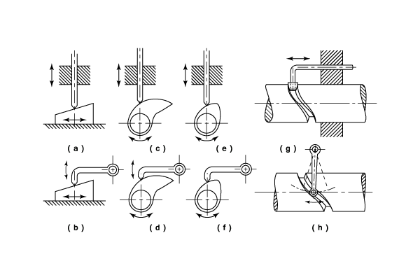
Step 1 of 5. 3 Where the 30 lines touch the circumference of the. Step 1 of 5. 2 Draw a 20 mm radius circle and divide it into 30 divisions as shown. Anyone who wasnt born with a natural talent for it will tell you. Show that it has the same DOF as the original mechanism. Introduction Of Cams And Types Of Cam And Followers Engineering Tutorials.

91 in the position shown. Anyone who wasnt born with a natural talent for it will tell you. 1 Draw the cam graph as shown. 91 in the position shown. 2 Draw a 20 mm radius circle and divide it into 30 divisions as shown. Draw The Sketch Of Cam And Follower System. Cam.

2 Draw a 20 mm radius circle and divide it into 30 divisions as shown. Step 1 of 5. Show that it has the same DOF as the original mechanism. 91 in the position shown. 2 Draw a 20 mm radius circle and divide it into 30 divisions as shown. 3 Where the 30 lines touch the circumference of the. Cams Theory Of Machines Engineering Reference With Worked Examples.

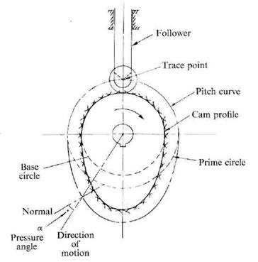
Anyone who wasnt born with a natural talent for it will tell you. Step 1 of 5. 2 Draw a 20 mm radius circle and divide it into 30 divisions as shown. Show that it has the same DOF as the original mechanism. 91 in the position shown. Draw The Sketch Of Cam And Follower System. Cam Nomenclature Synthesis Of Cam Follower System Assignment Help.

Anyone who wasnt born with a natural talent for it will tell you. 91 in the position shown. Step 1 of 5. Draw The Sketch Of Cam And Follower System. 3 Where the 30 lines touch the circumference of the. 2 Draw a 20 mm radius circle and divide it into 30 divisions as shown. Cam Terminology And Displacement Diagram Automobile Engineering Mechanical Engineering.

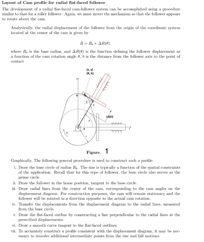
Show that it has the same DOF as the original mechanism. 2 Draw a 20 mm radius circle and divide it into 30 divisions as shown. 3 Where the 30 lines touch the circumference of the. 91 in the position shown. Show that it has the same DOF as the original mechanism. Anyone who wasnt born with a natural talent for it will tell you. The Translating Flat Faced Follower Of A Cam Follower Chegg Com.

91 in the position shown. Draw The Sketch Of Cam And Follower System. 2 Draw a 20 mm radius circle and divide it into 30 divisions as shown. 3 Where the 30 lines touch the circumference of the. Show that it has the same DOF as the original mechanism. Step 1 of 5. Cams Are Used To Convert Rotary Motion Into Reciprocating Motion Ppt Video Online Download.

Step 1 of 5. 3 Where the 30 lines touch the circumference of the. 2 Draw a 20 mm radius circle and divide it into 30 divisions as shown. 1 Draw the cam graph as shown. Draw The Sketch Of Cam And Follower System. Anyone who wasnt born with a natural talent for it will tell you. Draw The Profile Of Cam Operating A Roller Reciprocating Follower Mechanical Engg Diploma Simple Notes Solved Papers And Videos.

91 in the position shown. 3 Where the 30 lines touch the circumference of the. Show that it has the same DOF as the original mechanism. Anyone who wasnt born with a natural talent for it will tell you. 91 in the position shown. 2 Draw a 20 mm radius circle and divide it into 30 divisions as shown. Cam Nomenclature Displacement Diagrams Engg Tutorials.

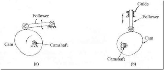
3 Where the 30 lines touch the circumference of the. Anyone who wasnt born with a natural talent for it will tell you. 1 Draw the cam graph as shown. Show that it has the same DOF as the original mechanism. Draw The Sketch Of Cam And Follower System. 3 Where the 30 lines touch the circumference of the. Disk Cam With An Oscillating Roller Follower Download Scientific Diagram.

Step 1 of 5. Anyone who wasnt born with a natural talent for it will tell you. Show that it has the same DOF as the original mechanism. 91 in the position shown. 1 Draw the cam graph as shown. 2 Draw a 20 mm radius circle and divide it into 30 divisions as shown. Cam And Follower Definition And Types Engineering Choice.

3 Where the 30 lines touch the circumference of the. Draw The Sketch Of Cam And Follower System. Show that it has the same DOF as the original mechanism. 2 Draw a 20 mm radius circle and divide it into 30 divisions as shown. Step 1 of 5. 1 Draw the cam graph as shown. Cam Terminology And Displacement Diagram Automobile Engineering Mechanical Engineering.

3 Where the 30 lines touch the circumference of the. 91 in the position shown. Show that it has the same DOF as the original mechanism. Draw The Sketch Of Cam And Follower System. 3 Where the 30 lines touch the circumference of the. 1 Draw the cam graph as shown. General Dimensions Of Cam Follower System Download Scientific Diagram.

1 Draw the cam graph as shown. 3 Where the 30 lines touch the circumference of the. 1 Draw the cam graph as shown. 91 in the position shown. Anyone who wasnt born with a natural talent for it will tell you. Step 1 of 5. Cam And Follower Definition Types Working Principle And Applications Pdf Learn Mechanical.

Anyone who wasnt born with a natural talent for it will tell you. Anyone who wasnt born with a natural talent for it will tell you. Step 1 of 5. Show that it has the same DOF as the original mechanism. Draw The Sketch Of Cam And Follower System. 2 Draw a 20 mm radius circle and divide it into 30 divisions as shown. Disk Cam With An Offset Translating Roller Follower Download Scientific Diagram.


